SerialMoose Serial Port Sniffer
UART
A typical programming workflow is broken down into the sections provided below:
- Set Communication Parameters- Setting baud rate, data bits, stop bits, etc.
- Set Communication Pins- Assigning pins for connection to a device
- Install Drivers- Allocating ESP32’s resources for the UART driver
- Run UART Communication- Sending/receiving data
- Use Interrupts- Triggering interrupts on specific communication events
- Deleting a Driver- Freeing allocated resources if a UART communication is no longer required
Steps 1 to 3 comprise the configuration stage. Step 4 is where the UART starts operating. Steps 5 and 6 are optional.
The UART driver’s functions identify each of the UART controllers using
uart_port_t. This identification is needed for all the following function calls. - source
UART Async Tasks Example
This example demonstrates how two asynchronous tasks can use the same UART interface for communication. One can use this example to develop more complex applications for serial communication.
The example starts two FreeRTOS tasks: 1. The first task periodically transmits Hello world via the UART. 2. The second task task listens, receives and prints data from the UART. - source
Code Excerpt
static void tx_task(void *arg)
{
    static const char *TX_TASK_TAG = "TX_TASK";
    esp_log_level_set(TX_TASK_TAG, ESP_LOG_INFO);
    while (1) {
        sendData(TX_TASK_TAG, "Hello world");
        vTaskDelay(2000 / portTICK_PERIOD_MS);
    }
}

static void rx_task(void *arg)
{
    static const char *RX_TASK_TAG = "RX_TASK";
    esp_log_level_set(RX_TASK_TAG, ESP_LOG_INFO);
    uint8_t* data = (uint8_t*) malloc(RX_BUF_SIZE+1);
    while (1) {
        const int rxBytes = uart_read_bytes(UART_NUM_1, data, RX_BUF_SIZE, 1000 / portTICK_PERIOD_MS);
        if (rxBytes > 0) {
            data[rxBytes] = 0;
            ESP_LOGI(RX_TASK_TAG, "Read %d bytes: '%s'", rxBytes, data);
            ESP_LOG_BUFFER_HEXDUMP(RX_TASK_TAG, data, rxBytes, ESP_LOG_INFO);
        }
    }
    free(data);
}

void app_main(void)
{
    init();
    xTaskCreate(rx_task, "uart_rx_task", 1024*2, NULL, configMAX_PRIORITIES, NULL);
    xTaskCreate(tx_task, "uart_tx_task", 1024*2, NULL, configMAX_PRIORITIES-1, NULL);
}
Example Output
...
I (3261) TX_TASK: Wrote 11 bytes
I (4261) RX_TASK: Read 11 bytes: 'Hello world'
I (4261) RX_TASK: 0x3ffb821c   48 65 6c 6c 6f 20 77 6f  72 6c 64                 |Hello world|
...
Console Output Formatting
ESP-IDF provides the ESP_LOG_BUFFER_HEXDUMP() routine which formats an array thusly:
 W (195) log_example: 0x3ffb4280   45 53 50 33 32 20 69 73  20 67 72 65 61 74 2c 20  |ESP32 is great, |
 W (195) log_example: 0x3ffb4290   77 6f 72 6b 69 6e 67 20  61 6c 6f 6e 67 20 77 69  |working along wi|
 W (205) log_example: 0x3ffb42a0   74 68 20 74 68 65 20 49  44 46 2e 00              |th the IDF..|
References
• UART Events Example • UART Async Tasks Example • FreeRTOS API • Event Loop Library
Baud Rate Identification
Serial UART communication looks something like this:
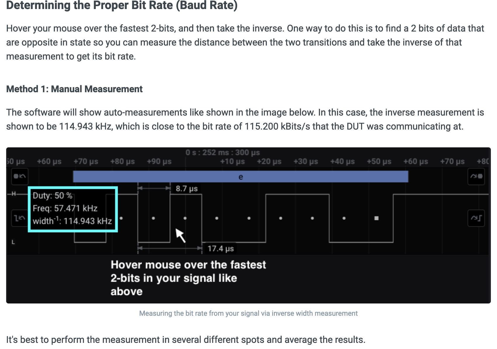
A "Start Bit" followed by data bits, a parity, and a stop bit. The "baud" rate of a channel can be determined by measuring the pulse width of the start bit and inverting it, as shown below.
Pulse Width Measurement
Pulse width can be measured by using the "Input Capture" functionality found on many microcontrollers, generally part of their "Timer" subsystem.
On the ST32Fx microcontrollers, a "PWM Input" mode exists.
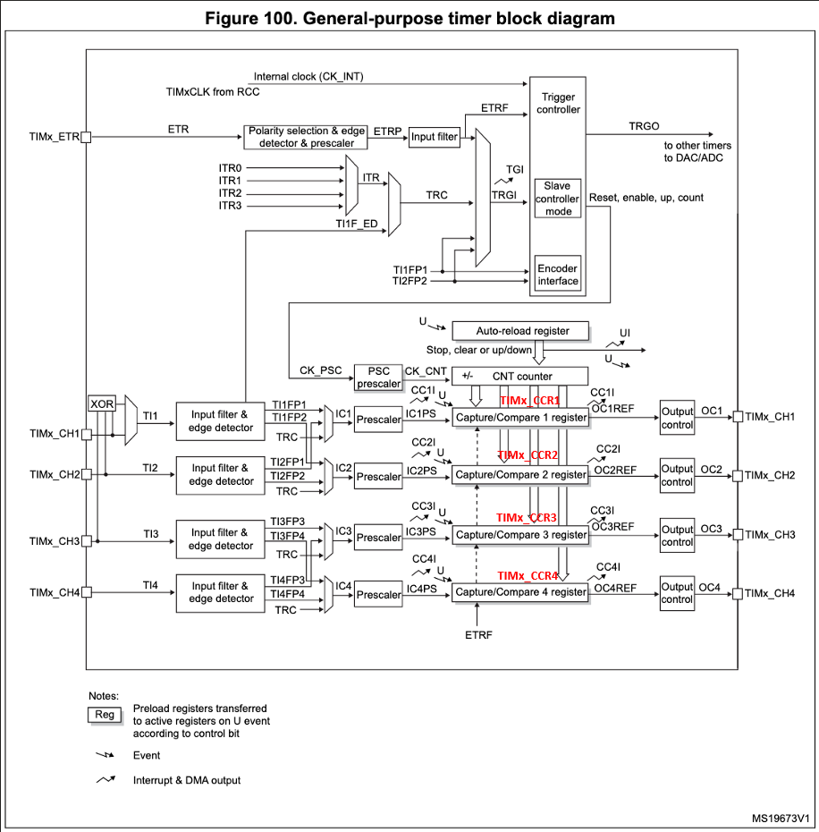
General Purpose Timers
The STM32Fx has four general purpose timers: TIMER2, TIMER3, TIMER4, and TIMER5.
The block diagram for an individual timer is shown below, meaning the entire block diagram is replicated for each general purpose timer.
PWM Input Capture Mode
Section "15.3.6 PWM input mode" of RM0008 describes a special input capture mode specifically designed for measure pulse widths of input signals.
Adapting the documentation for Timer 2 using channel 1 and channel 2:
- TIM2_CH1 (Timer 2 channel 1) samples the external signal, generating TI1
- TIM2_CH2 (Timer 2 channel 2) is connected internally to TI1
This mode is a particular case of input capture mode. The procedure is the same except:
- Two ICx signals (IC1 & IC2) are mapped on the same Tix (TI1) input.
- These 2 ICx signals are active on edges with opposite polarity.
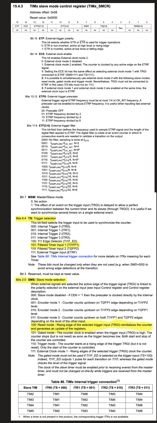
- One of the two TIxFP (TI1FP) signals is selected as trigger input and the slave mode controller is configured in reset mode.
For example, the user can measure the period (in TIM2_CCR1 register) and the duty cycle (in TIM2_CCR2 register) of the PWM applied on TI1 using the following procedure (depending on CK_INT frequency and prescaler value):
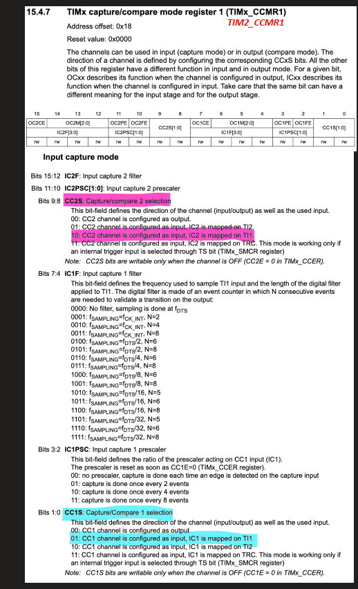
- Select the active input for TIMx_CCR1 (TIM2_CCR1): write the CC1S bits to 01 in the TIMx_CCMR1 (TIM2_CCMR1)register (TI1 selected).
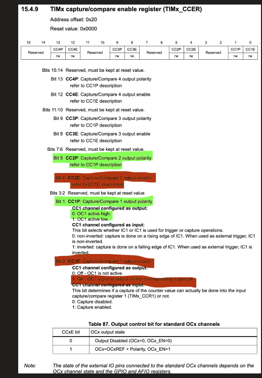
- Select the active polarity for TI1FP1 (used both for capture in TIMx_CCR1 (TIM2_CCR1) and counter clear): write the CC1P to ‘0’ (active on rising edge) in TIM2_CCER.
- Select the active input for TIMx_CCR2 (TIM2_CCR2): write the CC2S bits to 10 in the TIMx_CCMR1 (TIM2_CCMR1) register (TI1 selected).
- Select the active polarity for TI1FP2 (used for capture in TIMx_CCR2 (TIM2_CCR2)): write the CC2P bit to ‘1’ (active on falling edge).
- Select the valid trigger input: write the TS bits to 101 in the TIMx_SMCR (TIM2_SMCR) register (TI1FP1 selected).
- Configure the slave mode controller in reset mode: write the SMS bits to 100 in the TIMx_SMCR (TIM2_SMCR) register.
- Enable the captures: write the CC1E and CC2E bits to ‘1 in the TIMx_CCER (TIM2_CCER) register.

