ITead Maple
Overview
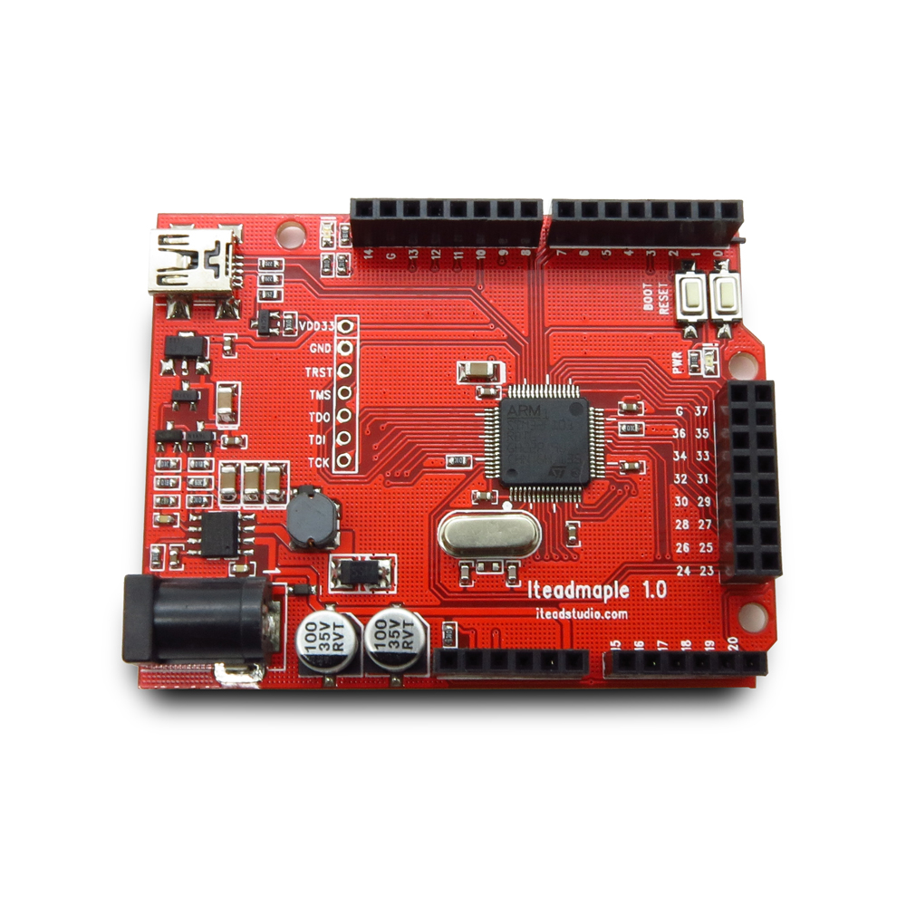
This board uses the STM32F103RBT6 chip, which is a medium-density chip.
- Tip: Pressing the 'Reset' button and immediately pressing the 'Boot' button puts the board in 'Perpetual bootloader mode', which gives you more time to upload sketches. - Pin 0 is Serial2 RX / Pin 1 is Serial2 TX
Arduino Setup
- Install board support:
- Extract 'Arduino_STM32' folder to ~/Documents/Arduino/hardware:
- SUPER IMPORTANT: Run 'install_drivers.bat' in drivers/win subfolder.
- Install the Arduino SAM boards (Cortex-M3) from the list of available boards.
- Reference: : https://github.com/rogerclarkmelbourne/Arduino_STM32/wiki/Installation
- Use "Maple (Rev 3)" board:

Updating Bootloader
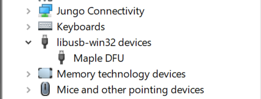
To use this board with Arduino, you need to do two things: 1. Install board support (see above section): 2. Install the STM32duino bootloader: 1. Get the maple_rev5_boot20.bin here 2. Burn using STLink or via a USB-to-Serial cable. 1. USB-to-Serial instructions NOTE: The original Maple bootloader can be found here 3. After burning the bootloader, the board should be blinking slowly and should show up in 'Device Manager' under 'libusb-win32-devices' as 'Maple DFU':  4. Running dfu-util -l should display the following:
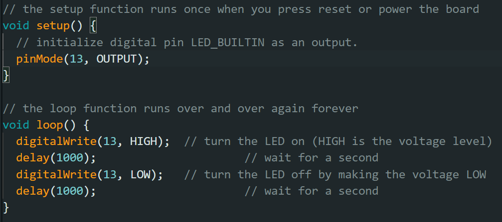
  5. Upload 'Blink' Sketch: - In Arduino, open the 'Examples/01. Basics/Blink' sketch and change the LED Pins:
  - Set the board configuration to 'Maple (Rev 3)'. - Compile the sketch. - Open a CMD window in
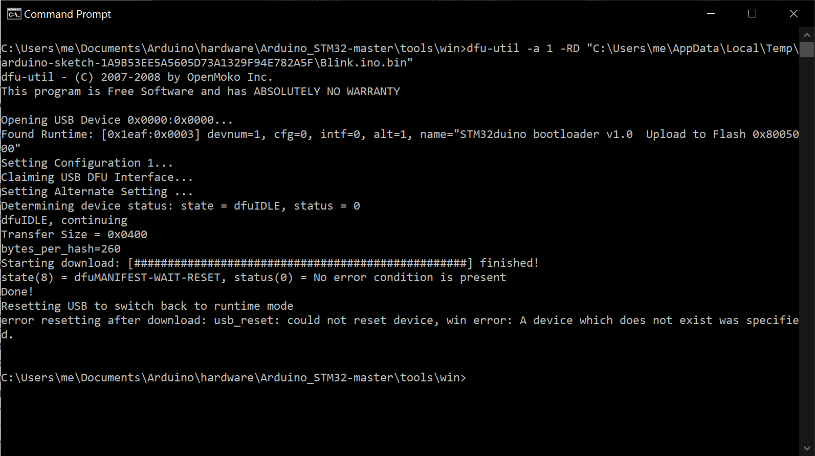
 Documents\Arduino\hardware\Arduino_STM32-master\tools\win and run: dfu-util -a 1 -RD "C:\Users\me\AppData\Local\Temp\arduino-sketch-1A9B53EE5A5605D73A1329F94E782A5F\Blink.ino.bin"
Using STLink
This board doesn't provide a SWD interface, however, section 2.3.24 of the STM32F103RBT6 datasheet mentions that the following pins are SWD pins:
- TMS -> SWDIO
-
TCK -> SWCLK
2.3.24 Serial wire JTAG debug port (SWJ-DP)
The Arm SWJ-DP Interface is embedded. and is a combined JTAG and serial wire debug port that enables either a serial wire debug or a JTAG probe to be connected to the target. The JTAG TMS and TCK pins are shared with SWDIO and SWCLK, respectively, and a specific sequence on the TMS pin is used to switch between JTAG-DP and SW-DP."
Before burning the bootloader, do a Target -> Erase Chip.


